What does off mean? A short course in using an intercom for beginners: how to connect a call to an apartment
This post will describe brief history some computer symbols that most of us see every day. The origin of some of them may already be familiar to you, but the origin of the rest is unlikely. In any case, who is interested in learning about what meanings the symbol ⌘ has, how the bluetooth symbol is connected to runes and where the @ symbol came to us from - welcome to cat.
Power
This symbol can be found on a huge number devices. During World War II, a binary system was used to designate power buttons: a one (1) meant “on” and a zero (0) meant “off.”
Originally, a broken zero with a one in the middle indicated unfinished activation and was used to indicate standby mode - this value was assigned to it in 1973. However, it was later decided that such a meaning could be confusing for users, and they gave it the meaning it has today: an on button. / off anything.
There are several types of symbol: on, off, on. / off, partial on / off (also used to indicate normal on/off)
At one time, “sleep mode” itself was a phenomenon that caused misunderstanding among consumers. It was difficult for people to digest the idea that a device could be both on and off at the same time. However, the innovation caught on, and an icon in the form of a crescent was proposed for it by the same Institute of Electronics and Electrical Engineers.
The appearance is not surprising: it completely describes the process for which it is responsible. At least, this standard is accepted in the USA and Europe, but in Japan you can find the image “Zzzz” (note: this is the sound that a sleeping person supposedly makes in comics).
This symbol was brought to IT by Apple - and precisely because it itself Steve Jobs decided to reduce the number of apple symbols on his company's products. At some point, Apple developers came up with a good and simple idea: to make a multitasking button on the keyboard that, pressed together with some other key, would call up a menu command. This would allow users to save time and issue commands directly from the keyboard.
Initially, the button was designated by the same logo that adorns all Apple products: a half-eaten apple. However, Jobs immediately hated the symbol, shouting: “There are too many apples on the screen! This is just funny! And the developers hastily set about redesigning the new button.
It was eventually realized by the artist Susan Kare. Moreover, the icon used for the Command button is not her personal design. Care discovered it in the dictionary of international symbols and signs, where it had a lot of very diverse and sometimes completely unexpected meanings.
So, this sign denotes an infinity loop, in Unicode and in the form of a car sign this symbol denotes a place of interest (“place of interest sign”), in some systems it is called the Gorgon loop, and in Sweden and others Scandinavian countries this symbol represents a tent camp.

Bluetooth
In the 10th century, Denmark was ruled by a king such as Harald Blatand (Harald I Bluetooth), who united the conflicting Danish tribes into a single kingdom. The idea is that Bluetooth does the same thing with communication protocols, combining them into one universal standard. Most likely, this king received his nickname for his dark front tooth.
The first bluetooth looked like a tooth and had blue– in fact, this is reflected in the name, Bluetooth (from the English blue - “blue” and tooth - respectively, “tooth”). This caused an association with Harald in the mind of one of the developers, and they decided to make the icon from a combination of signs that denoted the initials of the ancient monarch. The resulting symbol is a combination of two Nordic (“Scandinavian”) runes: “Hagall” - an analogue of the Latin H and “Berkanan” - the Latin B.
The USB symbol is a tree-like block diagram, at different ends of which there are big circle, small circle, triangle and square. Various figures emphasize that USB is a universal interface.
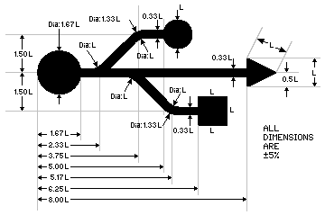
Initially, the prototype of the icon indicating the connection of other devices to a computer using USB technology was the trident of the ancient Roman deity Neptune (or Poseidon, your choice). Why exactly it is unknown, perhaps because it was considered one of the most powerful and omnipotent.
Play/Pause

These symbols came to the computer world from the world of audio and media players. They first appeared as symbols for controlling cassette decks in the 60s. Similar to playback, the fast forward buttons were designated as a double triangle. which could be either right- or left-handed: the direction of their tip indicates the direction of the rewind itself. Everything is simple and logical.
Regarding the pause sign, there is no exact data regarding the appearance. However, there are several hypotheses. The most likely of them is that the sign came to us from musical literacy, where it is called “caesura” and actually means a pause. According to another version, this is a stop sign from which the middle is cut out.
This symbol has a wide variety of names. We know him under the word “dog”. In France and Italy it is called “snail” (which, by the way, is the most logical name), in China it is called “little mouse”, in Germany, without bothering, it is called “monkey tail”.
The name “commercial at” takes its origin from English bills, for example, 5 widgets @ $2 each = $10, which translates as “5 items at $2 each = $10” (English at = “by”). Since this symbol was used in business, it was placed on typewriter keyboards and from there migrated to the computer.
In the USSR, this sign was unknown before the advent of the computer.
One version of the origin of the name “dog”: on alphanumeric monitors personal computers DVK series (1980s), the “tail” of the image of this symbol drawn on the screen was very short, which gave it a resemblance to a schematically drawn dog. The @ symbol was displayed every time the DVK computer was turned on, after which the user was required to select a boot loader.
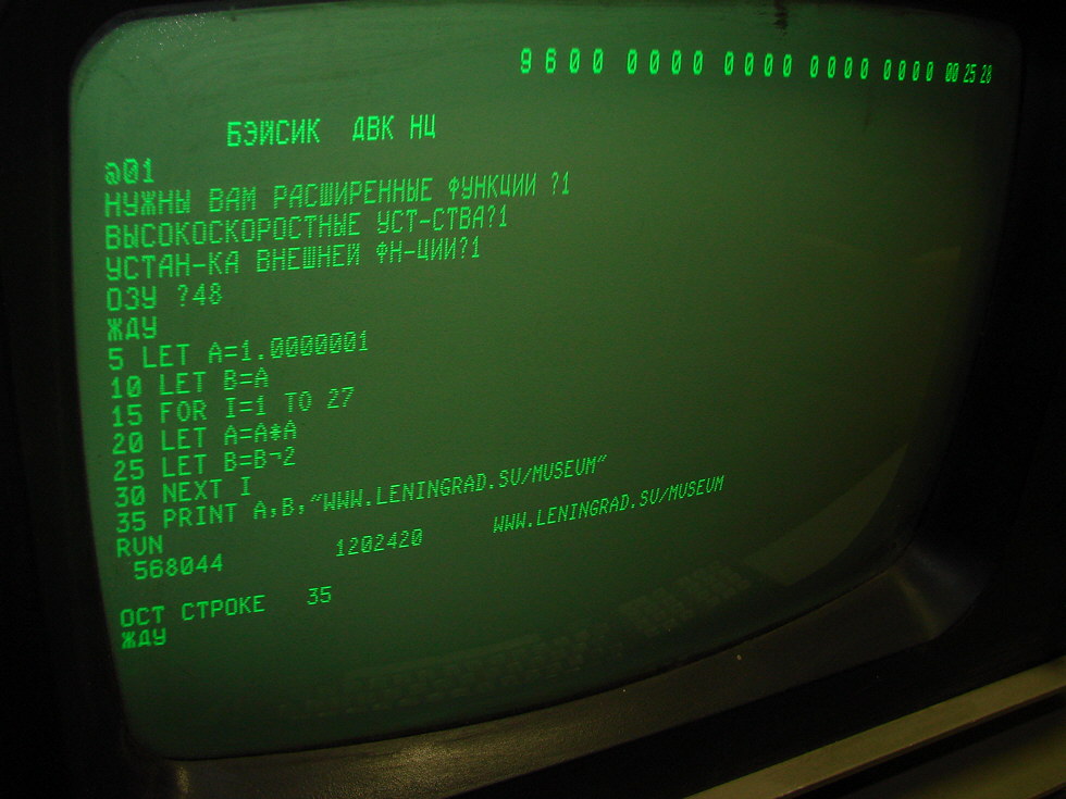
Also, the first Soviet users of computer networks could see this symbol on the Fidonet emblem, which depicts a dog, where the @ sign is located in the center of the muzzle and acts as a nose.
FireWire
We also owe this symbol to the developers from Apple. In 1995, a group of Apple developers - the main creators of FireWire - began creating a symbol that would accurately reflect the meaning of new technology. This interface, which was originally conceived as an alternative to SCSI, was attractive for its high (at that time) connection speed to digital audio and video equipment. Therefore, a symbol with three prongs was chosen to represent video, audio and data. Initially the sign was red, but later for reasons unknown to anyone the color was changed to yellow

This icon evokes some of the most vivid emotions among those who encounter it because... it notifies you about a frozen application or the entire system in Mac OS, and has many unofficial names. Among the censored ones: spinning pizza, hellish hypnowheel, spinning top of death, hypnotoad, and perhaps the most famous and almost official - the abbreviation SBBOD (from the English Spinning Beach Ball Of Death, literally: “spinning beach ball of death”).
The developers themselves—by the way, again from Apple—called their invention a “rotating wait cursor,” and, according to experts, it was intended as an alternative to the cursor with hourglass, which was used in early versions of Mac OS.
It originates in operating system NeXTstep. There he personified a rotating magneto-optical disk, from which the system and other applications loaded very slowly.
Ethernet

The Ethernet port symbol was created by David Hill of IBM. According to Hill, this symbol is part of a set of symbols that were intended to represent various connections local network, available in at the moment. It shows an array that is purposefully non-hierarchical and consists of computer elements or terminal elements.
Seasoned residents know very well how to use such a device, but beginners ask many questions about the operation of the intercom. This article will help owners understand their new device. In it you can find answers to several of the most frequently asked questions by users about the operation of this device.
What is an intercom
First, you need to briefly introduce the essence of the matter and explain to those who do not know what kind of miracle device this is - an intercom.
Intercom systems are used on entrance doors and the gate. They allow the owner of the home to personally control the access of persons to his home. Typically, such devices can most often be found on. They install intercoms that work with multiple subscribers.
The intercom allows you to protect the apartment and entrance from unwanted persons and bad companies, and this allows you to keep the stairwells clean and tidy. And products equipped with a video camera allow you to capture images of each visitor, which in the event of a robbery in the house will help identify the thief.
Operating principle and components
This device consists of several main parts and mechanisms. The elements that carry out the main operation of this system are:
- external calling panel;
- signal switch;
- tubes of internal panels;
- electromagnetic lock;
- exit button.
All these parts of the system are interconnected and work in the same way. The external panel provides communication with subscribers and allows access to a door locked with an electromagnetic lock. In turn, internal tubes help monitor the progress of events at the external panel through the built-in camera and remotely admit persons.
How to use this device
Intercoms appeared in the homes of residents of our country a long time ago. Someone deals with this device every day, so they know all its flaws and quality. And those who have not had to work with this device may be stumped, not knowing how to use the intercom.
First of all, the simplest question: how can a visitor contact the owner of the apartment?
When a person comes to visit, he will encounter such an action for the first time in his life. If the house is private, then it is most likely, almost 99%, that there is one single button on the calling panel. After pressing this button, a signal is transmitted to the house, accompanied by an audible warning from the system that a call is in progress. The owner, having heard a sound similar to a telephone call, must answer the call through the handset of the internal panel. Having previously familiarized himself with the guest through the speakers and microphones built into the system’s component panels, the owner can unlock the visitor’s lock by pressing a special button on the interior panel remote control. This button usually has a padlock design on it.
 Voice contact can be made between the external panel and the handset
 If a guest visited a friend living in apartment building, then you need to know the apartment number, dial its number on a special digital keypad of the external calling panel and press the call button. Further actions are the same as in the first case.
How can a tenant of the house gain access to the entrance?
Everything is clear with guests: you warn them in advance about the apartment number, they come, call the apartment and gain access to the house.
How can I get into the entrance without going through the electronic lock? Intercom systems are equipped with a reader for special keys in the form of a tablet. The key is applied to this niche, the microcontroller reads the code from the key, checks it with the database in its system and, if there is a match, gives access to the house.
 The electromagnetic lock can be opened with a key reader or by entering a PIN code
 For some reason, the owner of the apartment does not have a key. He moved into the house recently; upon purchase, he was given one copy of the key, but he lost it. In this case, you can, of course, call your neighbors a couple of times and ask them to open the door. But you shouldn't do that constant worry will not bring any good to the neighbors. To open a magnetic lock, you can enter an electronic code consisting of a combination of numbers, usually four characters. This code can be obtained from your neighbors or from the installation company. To do this you will need to present your registration.
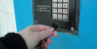
Does the intercom work and how not to miss a call?
Many novice users of this device ask how to understand that the intercom is on. The hostess is waiting for a guest or doctors and does not know if her intercom is working. How, then, not to ignore the arrival of visitors and not to make them wait, just because the intercom was turned off? Many intercoms are equipped with a button for switching the intercom operation status, but for some unknown reason they do not have the usual “on” signatures. and “off”, but are equipped with other marks – “stick” and “circle”. So, when the intercom is on: is it in the stick or circle position? It’s worth dotting all the I’s right away. Yes, you understood correctly, the stick is the English I, and the circle is O. These are abbreviations for English words IN and OUT, analogues of Russian ON. and OFF Therefore, with a stick, the intercom works, with a circle, it is turned off.
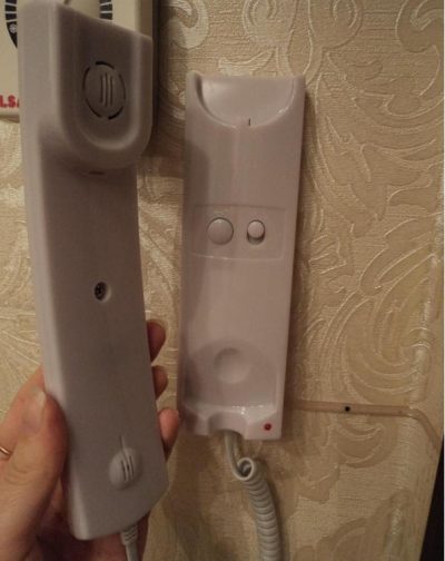 Some models do not have labels on the handset on/off button
 How to get out of the entrance?
It often happens that you go down the stairs to the entrance to the entrance, and it is so dark there that a person who does not know how to open the door from the inside may get confused. To open an electromagnetic or electromechanical lock indoors, a special button is installed at the level of the external panel, at a height of 1.3-1.4 meters. When you press it, a beep sounds and the lock unlocks.
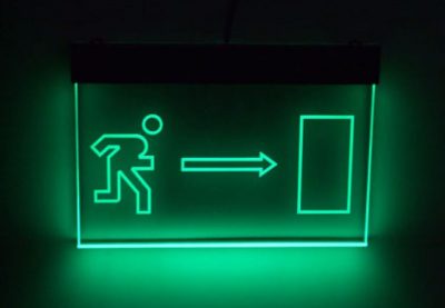 It’s difficult to find a way out in the dark; an illuminated exit button from the entrance will help with this.
 Important! The button for exiting the entrance is round, it has a backlight along the contour, but due to the fact that the sharp transition from a light room to a dark one does not allow a person’s eyes to see the color, it seems that there is no button.
I didn’t pay for the intercom, it was turned off, how can I connect the device myself?
Utility services can disconnect a certain apartment from the general system if the tenant does not pay the bills. It happens that residents who regularly pay utility bills are subject to such actions from utility workers.
You can disconnect a tenant in various ways:
- deprive the possibility of calling a specific apartment;
- remove the key cipher from the database;
- disconnect the tube from the system mechanically.
Often, the subscriber is deprived of the opportunity to use the device in the first two ways. This is achieved by entering certain combinations into the software environment on the external panel.
So, if the key does not work, the apartment is not called, the bills are all paid, and there is no response from the relevant authorities to requests to restore the system, then you can resort to independent actions.
Let's consider an example for one of the most popular systems - Vizit. If public utilities Removed the ability to call your apartment, you need to do the following.
There is a system switchboard at the entrance; you need to open it and get to the board in the block. It has a special jumper that is responsible for the state of the system mode. From the working state (work), it must be switched to programming mode (PRG). After this, you should go to the calling panel and enter the required combination of numbers. The input process will be accompanied by sound signals.
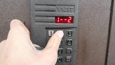 Programming environment on the Vizit device
 - #999. The intercom will beep twice and “1-2” will appear on the display.
- You need to enter the installation environment, to do this press 1. One beep, display status: “P_SE”.
- Among all the installation options numbered 8 is the service for turning on and off calling an apartment. Accompanied by a single signal, “A__” appears on the display.
- Next, enter the apartment number. The number of characters is from 1 to 3. If the apartment number is one-digit or two-digit, then after the number you need to enter #; if it is three-digit, the hash is omitted.
- 1 – turn on the apartment call, this will be displayed on the display as ON and a double beep from the system.
- * – saves and exits the settings environment.
You can check the implementation of the apartment call.
If the key does not work, but should be in good condition, then most likely it has been removed from the system database. To return the key to the base, you also need to put the system into programming mode using a jumper on the board. Enter the following combination on the panel, which will also be accompanied by sound signals.
#999 (double beep) 1 (single beep) 3 (more beep) APARTMENT NUMBER #
Attention! If the apartment number is three-digit, then you do not need to enter a hash at the end.
This combination prepares the system to record the key cipher in order to enter it into memory. If after entering this combination the message FULL appears on the display, accompanied by four beeps, then the memory is full and the key will not be recorded. If after entering the apartment number a single beep sounds, then the system is ready to remember the key.
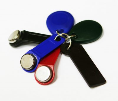 It is best to have several additional keys in case they are lost or disconnected from the database
 You must attach a key to the reader. If a double beep sounds and YES appears, the key has been written successfully. If there are several keys, then they can be applied one after another. The main thing is to save all actions at the end by entering *.
Learning to use an intercom and learning new things is not so difficult. Don’t be scared and think that this device can only bring inconvenience; in fact, you need to understand that it makes life much easier and adds safety to all residents.
As you can see, the switch is placed in the break of the phase wire going to the lamp. That's why in a socket with electrical wiring for a single-key switch, there are two wires.
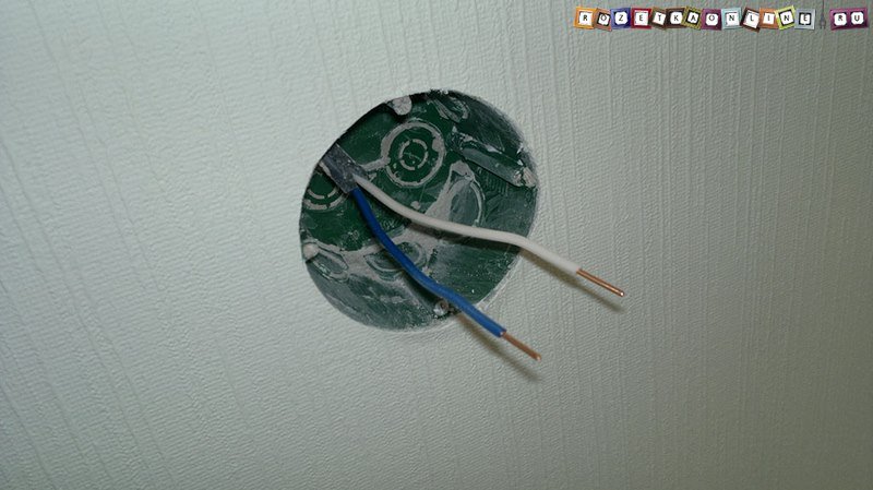
The first one, let’s call it “A”, goes to the switch from the electrical panel and always energized.
The second, let's call it “B”, goes from the switch to the lamp.
When you press the switch key, conductors “A” and “B” are connected, voltage flows freely to the lamp and the lamps in it light up. Accordingly, when the key is lowered, the contact breaks and the light goes out.
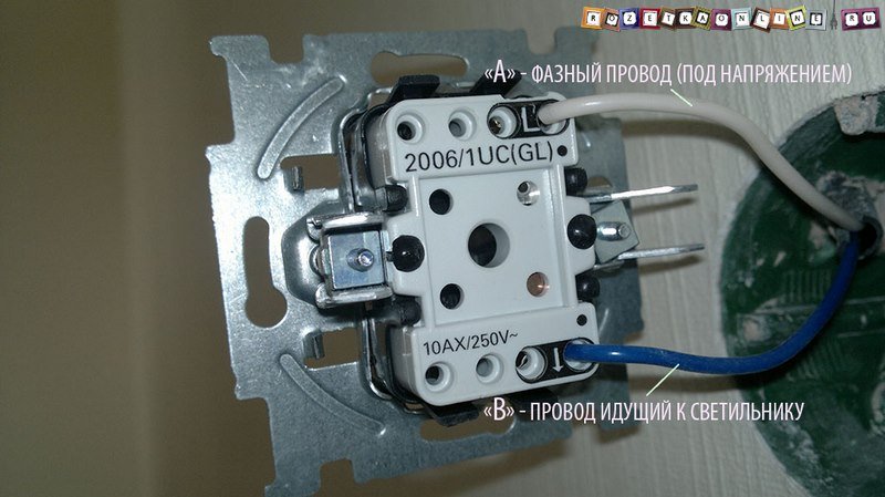
Now, if we remember the basic symbols in electrical engineering that we looked at (there are not many of them, I advise you to familiarize yourself with them in the future), it becomes clear what the “L” marking on the switch contact means.
The designation “L” on the switch indicates the contact for connecting the phase wire. The same wire “A” in our diagram, which comes from the electrical panel and is always energized.
Determining which of the wires in the socket box needs to be placed in terminal L of the light switch is quite simple - just check, for example, with an indicator screwdriver, which of the conductors has voltage - that will be the desired phase wire “A”.
The remaining, free, contact of the single-key switch, which can be marked in different ways: L1, L`, an arrow, “1” or nothing at all, is connected to wire “B” from our circuit, which goes directly to the switch.
You can read in quite some detail about how to properly connect a single-key switch, with a description of not only its contacts and the order of connecting the wires, but the entire installation process.
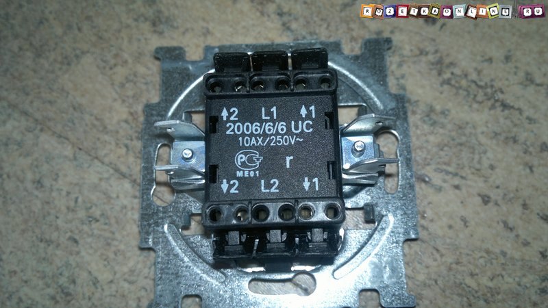
If, when examining the terminals of the light switch, in addition to the designations L and L1, you came across contacts with some kind of markings, then most likely you are dealing with a two- or three-key switch.
When determining the purpose of contacts, for example, a two-key switch, the same logic works, let's look at its diagram.
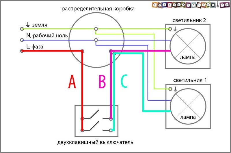
When connecting a two-key switch, three wires are used, which are available when installed in a socket box, are:
“A” is a phase wire coming from the electrical panel and is always energized. Connects to pin L of a two-gang switch.
“B” is a conductor going to the first lamp, or turning on the first mode of operation of the chandelier. Connects to terminal L1, L` or simply “1” of the light switch.
“C” is a wire going to the second lamp or turning on the second mode of operation of the same chandelier. Connects to terminal L2, L`` or simply “2” of the light switch.
I think now general principle The markings of all light switches are clear to you. More details on how to connect a two-key switch, which wires should be connected and where, are described.
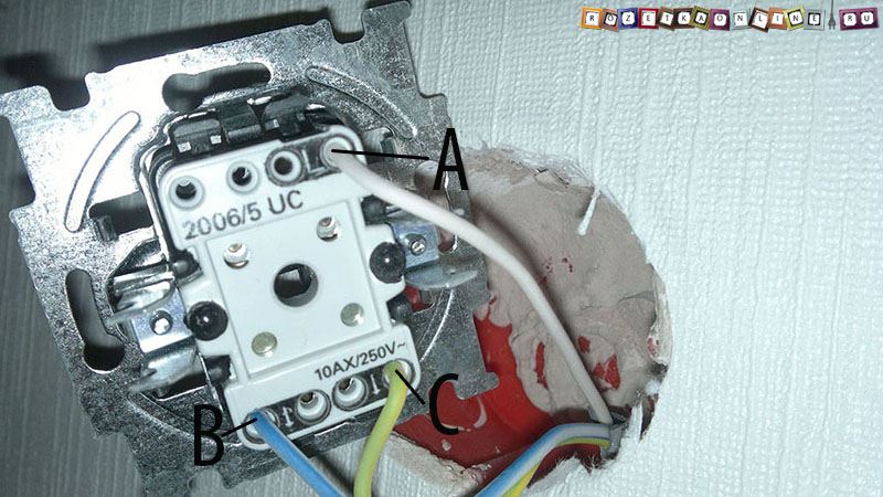
Contact L - this is always the place to connect the phase wire .
The remaining contacts (L1, L2, L3), most often numbered in order, refer to the corresponding switch keys, pressing which will light the lamp connected to the terminal of this key.
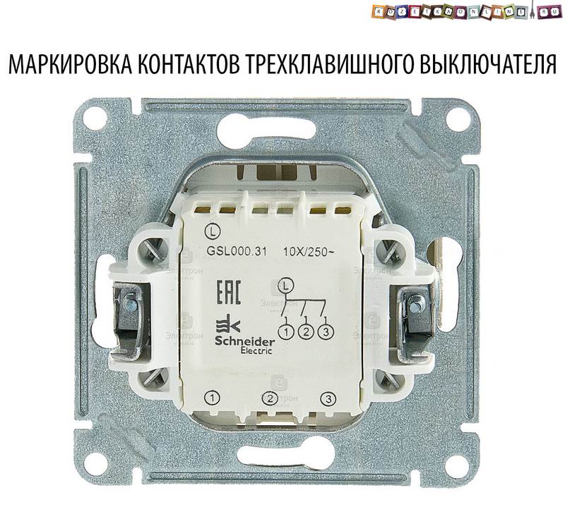
Determine which wire is responsible for turning on which of the lamps, without special equipment, quite difficult. Therefore, their connection is usually revealed experimentally.
By alternately connecting free conductors with the phase wire in the socket box, you will be able to notice which lamps are lit. In other words, you can connect the switch arbitrarily (except for the “L” terminal) and, if the keys are mixed up, simply swap the wires in terminals L2 and L3 if the switch is a two-key switch.
If there are three or four contacts for connection, and the light switch is one-key, or there are six contacts, and the switch is two-key, then you are most likely holding one of the types of switches in your hands.
Pass-through switch connection diagram- you can see three contacts for connecting wires for a single-key device. Two-key switch- six terminals for connecting wires.
Cross switch connection diagram- four contacts for connecting wires for a single-key model -.
Still have questions? - Write in the comments to the article, I will try to answer and help as quickly as possible. In addition, I will be glad to see any additions, corrections, criticism, etc.
Reading alphanumeric designations of electrical circuit elements
On all types of circuits, any element - a resistor, contactor coil, measuring device, etc., has an alphanumeric designation.
This designation consists of one or two letters and numbers. The letter(s) denotes-
indicate the code of this element, and numbers (digits) - serial number this element in this circuit.
For example, the alphanumeric designation KT2 means the following: KT - time relay, 2 - second in order in this circuit.
In the case of the image on the diagram components elements of electrical circuits
After the main digital designation, an additional one is placed through a dot, indicating
general serial number of this component.
In this case, the decoding of the designations of numbers and letters is carried out in reverse order, i.e. alphabetic characters and numbers are read from right to left.
For example, the alphanumeric designation KM5.4 means the following: KM – electromagnetic contactor coil, the serial number of the contactor in the circuit is 5, the serial number of the contactor contact in the circuit is 4.
This designation is read as follows: the fourth contact of the fifth electrical
magnetic contactor.
Rice. 1. Plus, positive polarity . To identify positive polarity connectors connecting a DC power source
Rice. 2. Minus, negative polarity. To designate negative connectors
significant polarity connecting the DC source
Rice. 3. Direct current. To designate connectors connecting the device -
ru to a direct current source, as well as to indicate that the equipment operates only on direct current
Rice. 4. AC. To designate connectors connecting the device
ru to the alternating current source, as well as to indicate that the equipment operates only on alternating current
Rice. 5. AC to DC converter. To denote pre-
AC to DC transformer and corresponding connectors
Rice. 6. DC to AC converter. To denote pre-
DC to AC generator and corresponding connectors
Rice. 7. Body, chassis. To identify connectors connected to the chassis or chassis
Rice. 8. Grounding, mass. To identify ground connectors
Rice. 9. Grounding, protective. To designate grounding connectors, I create
providing protection against electric shock
Rice. 10. Protection class II device. To designate equipment, the corresponding
meeting the safety requirements specified for class II equipment (protective
Rice. 11. Fuse. To identify fuse boxes and indicate their location
Rice. 12. Signal lamp. To designate a switch with which
turn the warning light on and off
Rice. 13. Lighting lamp, backlight. To designate switches, controls
shining a light source
Rice. 14. Enabled. To indicate the switching on of the network, power switches or their position corresponding to the switching on of the network
Rice. 15. Off. To indicate turning off the network, network switches or their position corresponding to turning off the network
Rice. 16. On/off, push-button switch with two fixed
bathroom provisions. To indicate a switch that turns on or off
network. Each switch position is fixed.
Rice. 17. Ready to turn on, standby mode. To indicate switch-
body (or its position), with the help of which part of the equipment is brought into
"Ready to turn on". On ships, the standby mode is called “stand-by.”
Rice. 18. Foot switch, pedal. To designate connectors to which
eye connects foot switch
Rice. 19. Program channel switch. To designate switches that control channel selection, program
Rice. 20. Start, launch, activation. To designate start, start, actuation switches
Rice. 21. Quick start. To designate a switch or control element
ment by which the operating speed (normal mode) is achieved without signi-
expected delay
Rice. 22. Stop, block. To denote a switch by means of which movement, for example, the movement of a tape, is stopped
Rice. 23. Quick stop, stop. To designate the control elements with the help of which the process, programs, or belt progress is stopped without significant delay
Rice. 24. Pause, break. To designate a switch whose action is re-
the movement (e.g. of the belt) is interrupted by the braking system and shutdown
Rice. 25. Effect or action in the direction of the starting point, normal mode. To indicate effect or action switches in the direction of action
real or imaginary starting point, sign, mark, for example, simultaneous reduction of several equipment parameters to pre-selected values
Rice. 26. Automatic control. To designate the switch (or its position) by which the equipment is brought into automatic control mode
Rice. 27. Manual control. To designate the switch (or its position) by which the equipment is put into manual control mode
Rice. 28. Remote control. To indicate a switch (or its position)
Rice. 29. Regulation. To designate an element to be regulated, setting the corresponding value of the quantity. The value of the quantity increases with the height of the figure
Rice. 30. Treble adjustment. To indicate adjustable
main elements of high sound frequencies
Rice. 31. Adjusting bass frequencies. To indicate adjustable
main elements of low sound frequencies
Rice. 32. Music. To indicate the "music" position of the "speech/music" switch
Rice. 33. Sound. To designate switches, controls and connectors related to audio information
Rice. 34. Balance. To indicate stereo channel balance adjustment
Rice. 35. Synchronization. To designate connectors, switches and controls
synchronizing elements designed to control equipment operating synchronously
but, for example, connecting a film projector synchronizer
Rice. 36. Filter (pass) high frequencies . To designate a high-quality filter
high frequencies, as well as associated switches and control elements
Rice. 37. Filter (pass) low frequencies . To identify a low-pass filter and its associated switches and controls
Rice. 38. Band-stop filter, notch. To indicate stripes
barrier filter, as well as associated switches and control elements
Rice. 39. Mid pass filter, bandpass. To designate a bandpass filter
ra, as well as associated switches and control elements
Rice. 40. Tuner, radio receiver. To designate connectors, switches and control elements of a radio receiver, tuner
Rice. 41 . Entrance. To designate input connectors when a distinction between inputs and outputs is needed
Rice. 42. Exit. To designate output connectors when necessary
between inputs and outputs
Rice. 43. Loudness compensation. To designate switches and control elements
cops that allow you to compensate for the physiological hearing curve
Rice. 44. Amplifier.
main elements of the amplifier. To designate an amplifier enclosed in a protective housing
Rice. 45. Clock, time relay. To designate switches and control elements in clocks, time relays, timers
Rice. 46. Monophonic, mono. To indicate monaural playback
recording (recording) sound. To indicate the "mono" position on the "mono/
stereo". Also used on record labels
Rice. 47. Stereophonic. To indicate stereophonic playback (recording) of sound. To indicate the "stereo" position on mono/stereo switches. Also used on record labels
Rice. 48. Tape recorder. To designate connectors, switches and adjustments
ing elements intended for a tape recorder
Rice. 49. Stereo tape recorder. To designate connectors, re-
switches and control elements intended for stereo magnetic
Rice. 50. Headphones. To designate connectors, switches and control elements intended for headphones
Rice. 51. Stereo headphones. To designate connectors, switches and control elements intended for stereo headphone
ical phones
Rice. 52. Headphones with microphone. To designate connectors, transfer
switches and control elements intended for headphones with a microphone
Rice. 53. Microphone. To designate connectors, switches and adjusters
building elements intended for microphones
Rice. 54. Stereo microphone. To designate connectors, switches
drivers and control elements designed for stereo microphones
Rice. 55. Earphone. To designate connectors, switches and adjustable
main elements intended for the earphone
Rice. 56. Speaker. To identify connectors, switches and control elements intended for a loudspeaker
Rice. 57. Recording (registration) on a storage medium. To denote re
switch its position in which the equipment is turned on for recording
Rice. 58. Playing a recording from a storage medium. To denote re-
switch or its position in which the equipment is turned on for playback from a storage medium
Rice. 59. Erasing a recording from a storage medium. To indicate switch
la or its position in which information recorded on the media is erased
Rice. 60. Control of input data during recording or registration on the wearable
body of information. To designate a control element by which input data is controlled during recording or registration
Rice. 61. Control of input data after recording or registering them on the device
body of information. To designate a regulatory element by means of which control of input data is carried out after recording or registering them
Rice. 62. Control of input data during its playback. To denote
the value of the regulatory element by means of which the input is controlled
data during playback
Rice. 63. Record lock. To designate the control element, I block
circuit designed to prevent accidental playback of a recording.
Rice. 64. Marker (marker). To designate a control element, using
cabbage soup whose mark (for example, signal, perforation, special code) can be reserved
registered on storage media
Rice. 65. Media cutoff. To designate the control element of the system from -
cutting, for example, in devices for copying and mounting paper, magnetic, perforated
roved tape
Rice. 66. Direct and alternating current. To designate connectors, connect
connecting equipment to a source of direct or alternating current, as well as to indicate
understanding that the equipment operates on direct and alternating current
Rice. 67. Quartz. To designate controls for quartz resonators
Rice. 68. On/Off, push-button switch with one fixed
bathroom position. To designate a switch that turns on or off
go network. Off position is fixed, "On" position carried out only when the switch is pressed
Rice. 69. Call. To indicate the switch that controls the bell
Rice. 70. Beep. To indicate the switch that controls beeps, sound
with alarms
Rice. 71. Fan. To indicate the switch that controls the fan
Rice. 72. Silent grounding. To indicate grounding connectors, both
ensuring minimal equipment noise from grounding
Rice. 73 . Equipotentiality. To designate connections intended to bring several pieces of equipment to a single potential
Rice. 74. Rectifier (no type specified). To identify connectors and control elements associated with rectifier devices
Rice. 75. Transformer. To designate connectors, switches and adjustments
lyrating elements designed to control power transformers
Rice. 76. Movement in one direction
ment, as a result of which the object moves in the specified direction
Rice. 77. Movement in two directions. To designate the regulating element
ment, as a result of which the object moves in two specified directions
Rice. 78. Movement restricted in two directions. To designate elements
one, as a result of which the object moves in two directions in a certain
within limits
Rice. 79. Action from the starting point. To designate the regulating element,
through which an object (effect) moves from the original (real or imaginary) point
Rice. 80. Action towards the starting point. To indicate regulation
element through which the object (effect) moves to the original (real or imaginary) point
Rice. 81 . Action in two directions from the starting point. To denote regu
lyrating element, through which the object (effect) moves from the original (real or imaginary) point
Rice. 82. Sequential action from the starting point and back. To denote
of the regulating element through which subsequent movement occurs
transfer of an object (effect) from a starting point (real or imaginary) and back
Rice. 83. Simultaneous action from the starting point and back. To denote
tion of the regulatory element through which simultaneous change occurs
moving an object (effect) from the starting point and back
Rice. 84. Setting the minimum. To designate the regulating element, in the middle
which sets the minimum value of a quantity, for example, the balance of a bridge circuit, the minimum deviation of a measuring device, indicator, etc.
Rice. 85. Setting the maximum. To designate a regulating element,
by means of which the maximum value of a quantity is set, for example,
construction, maximum deviation of the measuring device, indicator, etc.
Rice. 86. Notch resonant filter (wave trap). To indicate
values of the regulating element that controls the notch resonant filter
Rice. 87. Band-stop filter with variable stop band
(bandwidth). To designate a regulatory element that controls
Variable bandpass filter
Rice. 88. Bandpass filter with variable center frequency. To designate the control element that controls a variable center frequency bandpass filter
Rice. 89. Bandpass filter with variable bandwidth (selective control). To designate the control element that controls a variable-bandpass filter
-
 April 17, 2015In p Svobodin quartermaster 1st rank
 -
 April 17, 2015Beginning of the reign of Alexander I
 -
 April 17, 2015When a corrective alcohol return may be required


