Typical circuits of high-frequency generators. Signal generator: DIY function generator
Amateur radio components Two-transistor quartz generator Generator(see figure) can be useful when setting up various AM and FM amateur receivers. It consists of quartz and low frequency generator ov, made respectively on transistors T2 and T1. The low frequency signal through transformer Tr1 affects high frequency signal. When using quartz at a frequency of 8 MHz, the modulated signal is clearly audible at the eighteenth harmonic (144 MHz). The type of modulation in this case is mixed - AM and FM. Modulating signal frequency generator and approximately 1 kHz. The resistance of the primary winding of the transformer is 300-500 Ohms, and the secondary winding is 2.5-8 Ohms. Choke Dr1 is wound on a resistor with a resistance of 100 Ohms. Radio REF (France), 1974, N 4 Editor's note. Transistor OS44 can be replaced with P422. and AC132 to MP41A. Choke Dr1 should have an inductance of about 100-500 μH. As transformer Tr1, you can use the output transformer from pocket transistor radios. RADIO N 6, 1975, p.60 1...
Homemade CNC machine New!
Amateur Radio Technology - Homemade CNC machine (Author: Roman Vetrov, vetrovroman&mai1‚ru) Introduction A CNC machine designed and manufactured independently can carry out mechanical processing (drilling, milling) of plastics and textolite. Engraving on steel. Can also be used as a plotter, you can draw printed circuit boards. = Homemade CNC machine Fig.1. Homemade CNC machine (appearance) The accuracy of the machine is 0.0025 mm per step, but in fact (taking into account the inaccuracy in the manufacture of machine components, the gaps in the components, in the screw-nut pair) the accuracy is 0.1 mm. Machine without feedback, i.e. The position of the tool is monitored by software; stepper motors are responsible for the accuracy of movement. The machine connects to the computer via an LPT port and runs under Windows 98 and XP. Mechanical part = Homemade CNC machine Fig.2. Homemade CNC machine (mechanical part) The body parts of the machine are made of vinyl plastic b=10mm. Guides are round, ground rods. The calipers are made of textolite (with holes for guides). Screw – pin with M6 thread (pitch t=1mm). The nuts are fluoroplastic (later they were replaced with bronze ones because with such sizes the losses due to friction in a bronze nut are less). Electrics Electrics can be divided into three parts: Power supply; Controller; Driver. = Homemade CNC machine Fig.3. Homemade CNC machine (electrical part) Power supply: 12V 3A – for powering stepper motors and 5V 0.3A for powering controller chips. Controller: The developed controller can serve up to 32 (in my circuit 3) stepper motors in series, i.e. Only one motor can run at a time. Parallel operation of the engines is ensured by software. The stepper motor management controller is assembled on 555TM7 series microcircuits (3 pcs). Does not require firmware. The electrical circuit of the controller is shown in Fig. 4 1...
STABLE RF GENERATOR
Amateur radio components STABLE GENERATOR HF O. BELOUSOV 258600. Ukraine, Cherkasy region, Vatutino, Kotovsky str., 10. Proposed generator operates in the frequency range from 26560 kHz to 27620 kHz and is intended for tuning CB equipment. The signal voltage from "Output 1" is 0.05 V into a 50 Ohm load. There is also "Out.2". to which you can connect a frequency meter when setting up receivers. IN generator There is no possibility of receiving frequency-modulated oscillations. For this purpose, use “Input mod.”, to which a low-frequency signal is supplied from an external audio frequency generator. Nutrition generator and is produced from a stabilized source of +12 V. The current consumption does not exceed 20 mA. Master generator made on field-effect transistors VT1. VT2. connected according to the "common source - common gate" circuit. Generator, assembled according to this scheme, works well at frequencies from 1 to 100 MHz. because it uses field-effect transistors with a cutoff frequency >100 MHz. According to research conducted. the same one generator has short-term frequency instability (for 10 s) better than generator s, made according to capacitive and inductive three-point circuits. Frequency drift generator and for every 30 minutes of operation after a two-hour warm-up, as well as the levels of the second and third harmonics are less than generator ov, made according to the three-point scheme. Positive Feedback generator This is carried out by capacitor C10. The VT1 gate circuit includes an oscillatory circuit C5...C8. L1. determining the generation frequency of the circuit. Through a small capacitance C9, a varicap matrix VD1 is connected to the circuit. By applying a low-frequency signal to it, we change its capacitance and thereby carry out frequency modulation generator A. Nutrition generator and VD2 is additionally stabilized. High frequency the signal is removed from resistor R6. included in the source circuits of transistors. TO generator a broadband emitter follower is connected to VT3 and VT4 through capacitor C 11. The advantages of such a repeater are given in. A voltage divider (R14.R15) is connected to its output through capacitor C 15. The output resistance at "Output 1" is 50 Ohms. therefore, using a coaxial cable with a characteristic impedance of 50 Ohms, you can connect cx1...
ULTRASONIC GENERATOR FOR RATS REPEARDING
Consumer Electronics ULTRASONIC GENERATOR FOR RATS REPEAL This generator can be used in grain storage facilities and other food storage areas. Scheme generator a, shown in the figure, consists of a low frequency modulator (C1, C2, DD1.1, DD1.2, R1, R2). generator and ultrasonic vibrations (SZ, C4, DD1.3, DD1.4, R3, R4), a power amplifier on transistors VT1...VT3 and a radiator, which is used as high frequency loudspeaker 4GDV-1. At the values indicated in the diagram, generator emits frequency-modulated oscillations in the range of 15...40 kHz. Frequency generator and is regulated by resistor R4, the modulation frequency is regulated by resistor R2 within the range of 2...10 Hz. It must be borne in mind that the ultrasonic vibrations emitted by this generator ohm, may have a negative impact on nervous system humans and domestic animals. Prolonged stay indoors with a worker generator om can cause headaches, nausea and other feelings of discomfort, so it is recommended to turn it on immediately before leaving the room. If you install contact S1 in such a way that in case of unauthorized entry into the premises, that same contact closes, generator can also work as a security siren, since it begins to emit frequency-modulated oscillations in the range of 1000...2000 Hz. It should be borne in mind that when working for a long time in one frequency range, rats can adapt, so it is necessary to change the radiation parameters with resistors R2 and R4 2...3 times a week. You can also use this technique: connect capacitor C4 to a piece of wire that creates an additional capacitance that changes with changes in temperature, humidity, wind force (if the wire is brought outside), etc. Then the frequency will change according to a random law. V.BORODAY, 330000, Zaporozhye, Tsentralny b., 12B-4.1...
UHF SIGNAL GENERATOR
Measuring technology GENERATOR UHF SIGNAL When setting up amateur radio structures operating at frequencies above 1 GHz (for example, in the amateur band 23 cm), it is necessary generator highly stable signal. It is not difficult to make if the radio amateur has at his disposal a quartz resonator with a frequency of 27...50 MHz. Schematic diagram generator a is shown in Fig. 1. Master generator assembled on transistor VT1, frequency multiplier - on diode VD1. The necessary harmonic of the original signal (for example, the 29th for the 23 cm amateur band when using a resonator at a frequency of 45 MHz) is highlighted by the L3C6 circuit. The bias voltage on diode VD1 is created automatically. Its optimal role (based on the maximum signal of the required harmonic) is set by trimming resistor R4. Using the same criterion, the level of high-frequency voltage supplied to the multiplier from the master voltage is selected (using trimming resistor R3). generator A. If necessary, output signal generator but it can be modulated. The required level of modulating voltage is set with variable resistor R5. Puc.1 V generator not applied normal high frequency diode (not intended for operation in the UHF range). If it is replaced with a Schottky diode, the output signal level will apparently increase. The oscillating circuit L1C2 is adjusted to the frequency of the quartz resonator. The design of coils L1 and L2 is not critical (the ratio of their number of turns is approximately 10). Choke 15 is a frameless coil (10 turns) with a diameter of 13 mm. Elements VD1, C4, C5, L3-L5 are mounted on a board made of one-sided foil material, placing all parts on the foil side. Circuit L3C6 is a half-wave line adjusted by a capacitor. Its dimensions for the 23 cm amateur band are shown in Fig. 2. A line is made from a copper strip, bent and soldered both ends to the foil. The communication loop L4 is bent from a wire with a diameter of 1 mm. and placed a few millimeters from the L3 line. Puc.2 By increasing the longitudinal dimensions of the line (in proportion to the decrease in operating frequency), described generator can be used for 1...
Pocket radio "Moscow"
Radio reception Pocket radio receiver "Moscow" At numerous requests from readers, the editors are re-publishing brief design data and a diagram of the amateur pocket radio receiver "Moscow" designed by V. Plotnikov ("Radio", No. 11, 1959). 1...
RADIO STATION WITH THREE TRANSISTORS
Radio transmitters, radio stations RADIO STATION WITH THREE TRANSISTORS The radio station is designed for two-way communication in the 27 MHz range with amplitude modulation. It is assembled using a transceiver circuit. The cascade on transistor VT1 serves as both a receiver and a transmitter. The amplifier on transistors VT1 and VT2 in the receiving mode amplifies the signal isolated by the receiver, and in the transmitting mode modulates the carrier. During installation, special attention should be paid to the location of capacitors C10 and C11. They are used to prevent self-excitation. If self-excitation does occur, then you need to connect several more capacitors of the same capacity. About setup. It's very simple. First, using a frequency meter, the frequency of the transmitter is set, and then the receiver of another radio station is adjusted for maximum noise suppression and maximum signal volume. Coil L1 tunes the transmitter, and coil L2 tunes the receiver. Tp1 - any small-sized output transformer. Ba1 - any suitable speaker with a winding resistance of 8 - 10 Ohms. Dr1 - DPM-0.6 or homemade: 75 - 80 turns of PEV 0.1 on a resistor MLT 0.5 W - 500 kOhm. The remaining parts are of any type. The coils are wound on frames with a diameter of 8 mm and contain 10 turns of PEV 0.5 wire. =Printed circuit board and circuit board - in Fig. 2 Printed circuit board and circuit board - in Fig. 2 TECHNICAL DATA Supply voltage - 9 - 12 volts Communication range in open areas - approximately 1 km. Current consumption: receiver -15 mA, transmitter - 30 mA. Telescopic antenna - 0.7 - 1m. Case dimensions - 140 x 75 x 30 mm. N. MARUSHKEVICH Minsk 1...
VHF-FM MICROTRANSMITTERS
Radio spy VHF-FM MICROTRANSMITTERS Micropower radio transmitters, the output power of which ranges from fractions to several milliwatts, can be used to organize radio communications and transmit data over a distance of several meters. The devices described below operate in the frequency range 66...74 MHz and, if necessary, can be reconfigured to operate in a different frequency range. All designs use highly efficient small-sized electret microphones of the MKE-332 type, containing a built-in field-effect transistor preamplifier. Figure 1 shows a diagram of a radio microphone, in the basic bias circuit of which an electret microphone is included as a controlled resistor. A piece of flexible stranded wire 20...40 cm long was used as an antenna. The current consumed by the device is approximately 1 mA. The device shown in Fig. 2 is a parallel-type telephone radio adapter and is designed to broadcast audio signals over a high-frequency channel. The device can be powered directly from a 60V telephone line, consuming up to 2mA of current; when removing handset(supply voltage drops) the radio microphone turns off. The circuit uses cascode connection of transistors, in which for low-frequency signals the load in the collector circuit of transistor VT2 is high frequency generator, made on transistor VT1. In turn, for currents high frequency in the emitter circuit of transistor VT1, an amplification stage on transistor VT2 is used. When powering the device from a telephone line, it is not necessary to connect an antenna, since the telephone line itself acts as a fairly extended antenna. Reception of high-frequency signals is possible using a portable FM receiver along a telephone line; When moving several meters away from the line, the signal quickly fades. The circuit provides for the possibility of autonomous or redundant power supply from a 9 V battery. In this case, the device becomes a regular radio microphone, and an antenna must be connected to it. The device is protected against incorrect connection of the power supply and against...
Tunnel diode crystal oscillator
Amateur radio components Quartz generator on a tunnel diode The figure shows simple circuit quartz generator and using a tunnel diode. The output power of the generator is several tens of microwatts. The operating mode of the tunnel diode is set using trimming resistor R1. Supply voltage 1-2 Volts. References: H.-J. Fischer, W. E. Schlegel. >Transistor- und Schaltkreis Technik. - Berlin, 1979.1...
Simple RM at 115...175 MHz
Radio spy Simple RM at 115...175 MHz A distinctive feature of the circuit presented in the figure is that the amplified 3H signal from the collector of transistor VT1 is supplied to the input generator and RF VT2 without a separation capacitance, which is why the operating point generator and for direct current it is determined by the operating point VT1, that is, resistor R2. The main task when setting up the device is to select the optimal ratio between current consumption generator a and the distortion factor in the 3CH path. It is advisable to use transistor VT2 high frequency type KT368, KT325. For a frequency of 175 MHz, the value of capacitance C4 is 6.8 pF, L1 - 5 turns of silver-plated copper wire with a diameter of 0.56 mm with a tap from the third turn. Winding diameter - 5mm. Communication coil L2 - 2 turns of PEV wire - 0.25 on top of L1. In order to reduce dimensions, this device uses a resonant antenna. To make such an antenna, you need to take a long plastic tube with a diameter of 3 mm and wind it in a row with PEL wire - 0.25 mm 65...70 turns. Then connect the antenna to the output generator and, unwinding one turn at a time, they control the resonance with a dial indicator of the field. The circuit operates in a wide voltage range from 1.5 to 15 V, and the frequency of output oscillations, when using a non-resonant antenna, changes within insignificant limits. With a current consumption of 10 mA, a receiver with a sensitivity of 1 µV allows you to listen to a radio microphone at a distance of up to 500 m.1...
VHF CONVERTER
Radio reception VHF CONVERTER E. RODIONOV, Minsk. The proposed converter (Fig. 1) is designed for receiving VHF radio stations operating in the frequency range 88...108 MHz (RM), on a receiver with a frequency range of 65.8...73 MHz. It is convenient to take power for the converter from the VHF receiver unit. By connecting the converter to the receiver and antenna, stretching or compressing the turns of the L2 coil, the receiver is tuned to the range. This process is repeated several times until high-quality reception of the FM radio station (88...108 MHz). In this case, the local oscillator frequency is approximately 30...35 MHz. Next, adjust the input circuit of the mixer, formed by inductance L1 and its interturn capacitance, compressing or stretching the turns of L1. Tuning frequency - 100...104 MHz. In many cases, the converter can be simplified by eliminating the coil L1 and capacitance C1. Container C4 can also be removed. In this case, the inductance L2 or the feedback capacitance SZ should be increased. The values of capacitances C1, C2, C5, C6 can be changed within a fairly wide range without loss to the para-meters of the converter. L2 is a winding wire 40 cm long, wound on a mandrel with a diameter of 4 mm. L1 - 10 turns on a mandrel with a diameter of 5 mm. Transistor VT1 is KT363; in extreme cases, it can be replaced with KT361. In this case, the sensitivity of the converter decreases noticeably. KT2 - KT315, can be changed to any high frequency transistor structure p-p-p. A drawing of the converter printed circuit board is shown in Fig. 2. The parts are soldered from the side of the printed conductors. The finished converter board in the receiver can simply be glued to the VHF unit or to the housing next to it.1...
Ramp voltage generator
Radio amateur designer Generator sawtooth voltage Generator, the circuit diagram of which is shown in the figure, allows you to obtain a sawtooth voltage of fairly high linearity. It is made on two operational amplifiers and one field-effect transistor with an insulated gate. The first operational amplifier MC1 is used to assemble generator rectangular pulses, the repetition rate of which is synchronized by the input pulses. The duration of the pulse and pause is determined by the charging and discharging time of capacitor C1. The capacitor is charged through resistors R1 and R2, and discharged only through resistor R1 (resistor R2 is shunted by diode D1). Diode D2 and zener diode DZ limit the positive voltage supplied to the input of field-effect transistor T1. The second operational amplifier MC2 contains an integrator, the operation of which is controlled by pulses coming from generator and rectangular pulses through an electronic switch (transistor T1). "Radio, television, electronics" (NRB), 1975. N 2 Note. IN generator e sawtooth voltage, you can use operational amplifiers K153UD1A and field-effect transistor KP301.1...
HIGH FREQUENCY CHOCKS
Components of amateur radio equipment HIGH-FREQUENCY CHOCKS In short-wave receiving and transmitting equipment, high-frequency chokes with inductance from several tens of microhenries to units of millihenries are widely used. If the radio amateur does not have standard chokes with a ferrite magnetic core (D-0.1, etc.), then you can use correction chokes for tube TVs (they are sometimes on sale as spare parts). So in unified second-class black-and-white TVs there are chokes with inductance of 39, 95, 140 and 360 μH. Usually they are coils wound in the “universal” way on high-resistance MLT-0.5 resistors (see Fig. 1, a). Fig. 1 These chokes do not have a ferrite magnetic core, so they (unlike the D-0.1 chokes) can also be used in circuits where relatively high high-frequency voltages operate, for example, in the pre-terminal and, moreover, sometimes in the final cascades of transmitting equipment. It is easy to make such chokes yourself. In Fig. 1, b is shown as an example homemade a choke with an inductance of 330 μH, designed for the printed circuit board of the Radio-76 M2 transceiver (the distance between the holes in the board for mounting is 15 mm). The design dimensions of the throttle are shown in Fig. 2. Fig. 2 It is wound on a bar with a cross section of 3X3 mm, made of sheet organic glass, polystyrene, fiberglass or any other good dielectric. In order not to damage the insulation of the wire, the ribs of the bar are rounded, and to prevent the turns of the coil from spreading, you need to install cheeks made of some kind of dielectric (in Fig. 2 they are shown as a dotted line, and in Fig. 1, b they are completely absent, they were removed after filling the coil with paraffin ). Two pieces of tinned copper wire with a diameter of approximately 0.8 mm - future ones - are pressed into the block. The required number of turns N can be estimated using the approximate formula N=32root(L/d), where L is the inductance of the inductor (μH), d is the diameter of the coil frame (mm). For frames with a square cross-section, the value 1.2a should be substituted in this formula for d, where a is the side of the square. For a choke with an inductance of 330 μH, you need to wind 310 turns with PEV wire or 1...
Pulse generator with independent phase control
Digital technology Generator pulses with independent phase control Roberta Tovar Medina. Institute of Applied Mathematics (University of Mexico, Mexico) In a phase-locked loop circuit, it is often necessary to have generator signal, the phase of which could be adjusted independently of other parameters. A circuit is proposed that consists of a 555 type timer and several discrete components and is generator pulses with independent and smooth phase adjustment ranging from 0 to 180°. rice. 1 Timer U1 (Fig. 1) with transistor Q1 and capacitor C1 generates a sawtooth signal, the extreme values of which are voltages Vcc/3 and 2Vcc/3 (Fig. 2). Each period of the sawtooth signal corresponds to a short pulse at the output of U1. This pulse switches the trigger Uз-a, which generates the reference signal QA. The signal from the output of the comparator, which compares the sawtooth signal with the reference voltage on the motor of the variable resistor R4, switches the NZ-b trigger, which generates QB pulses, phase-shifted relative to the reference ones. rice. 2 This phase shift is linearly dependent on the reference voltage at the non-inverting input of comparator U2, and the position of the R4 slider can be calibrated in phase units, with Vcc/3 corresponding to 0° and 2Vcc/3 to 180°. Since the flip-flop has two outputs, QB and QB, a signal can be obtained from the circuit both ahead and behind the reference phase. 1...
HIGH STABILITY RF GENERATOR (up to 200 MHz)
Short pulse generator for IR remote control
Consumer electronics Generator short pulses for IR remote control Author: Kalmykov Evgeniy ( [email protected]) In remote management systems based on IR rays of various devices, it is required to use generator s bursts of short pulses to ensure high pulse radiation power and good efficiency. Two options for implementing such devices are given below. The device shown in Fig. 1 works as follows. Generator rectangular pulses, collected on elements DD1, R1, C1, generates a sequence of pulses with a period depending on the constant circuit R1, C1. Next, the signal goes to counter DD2.1, which divides the frequency by 8 and generates short pulses. The duration of the pulses acting at output 8 of this counter is determined by the parameters of the R2C2 circuit. To form a burst, the sequence is fed to DD2.2, at output 4 of which a pulse of 70 μs duration with a repetition period of 0.7 s is generated. These pulses, together with short pulses from output 8 of DD2.1, are fed to a matching circuit made on the DD1.3 element, to the output of which an IR LED is connected through the VT1 switch. The device in Figure 2 is basically similar to the first, but the duration of the burst is different, since the signal comes to the DD1.3 component from a different output of the DD2.2 counter. Thus, by connecting the DD1.3 input to different DD2.2 outputs, you can get packs consisting of different quantities impulses. Published 12/15/2000 = Generator short pulses for remote control on IR 1...
QUARTZ GENERATOR
Amateur radio components QUARTZ GENERATOR In the process of designing amateur radio equipment, there is often a need for quartz generator e at one or more frequencies. Scheme of one of these generator ov, at three frequencies, is shown in the figure. It is made on four elements "2I-NOT". When a signal is generated, only two logic elements operate simultaneously in it: D1.4 (constant) and D1.1 (or D1.2 and D1.3, depending on the position of switch S1). Resistors R1-R4 provide a linear amplification mode for the “2AND-NOT” elements. At the output of element D1.4 there are rectangular pulses, the amplitude of which is approximately 3 V. To obtain a sinusoidal voltage, tori C4 - C6 are used to adjust the generation frequency, and resistors R5 - R7 are used to set and equalize the amplitudes of the input voltages. Given generator The authors used SSB to CW signals in shapers when creating a transceiver based on the R-250M2 radio receiver. It can be used at other frequencies, using quartz with a resonant frequency of 75...3000 kHz. Moreover, quartz may have a low quality factor. During installation generator and resistors R1-R3 should be placed as follows. as close as possible to the corresponding pins of the microcircuit. G. GULYAEV (UA4HLK ex UY5XS), G. CHLIYANTS (UY5XE), Kuibyshev - Lvov RADIO N 10, 1980 1...
RF ATTACHMENT FOR OSCILLOSCOPE
TWO-TONE ELECTRONIC SIREN
Digital technology TWO-TONE ELECTRONIC SIREN In Fig. Figure 1 shows a schematic diagram of an electronic siren assembled on one transistor and microcircuit. Essentially, sirens consist of three generator ov with different time characteristics. So. transistor V1, ingredient D1.1, capacitor C1 and resistors R1 - R3 form generator with a clock frequency of approximately 1 Hz. The desired signal repetition frequency can be selected using trimming resistors R2 and R3. Element D1.3, resistor R4. capacitor C2 and ingredient D 1.4 make up the second generator with a generation frequency of approximately 1000 Hz. And finally, ingredient D1.3 together with resistor R5, capacitor C3 and element D1.4 form the third generator, but at a lower frequency, approximately 200 Hz. The final load of the siren is loudspeaker B1, connected to the output of element D 1.4. "Eltktrotehnicar" (SFRY), 1976, N 7 Note. In a two-tone siren, you can use the K155LA3 microcircuit and any low-power silicon pnp transistor, for example KT315B,1...
SIMPLE WIDEBAND RF SIGNAL GENERATOR
Simple stereo generator
Measuring technology Simple stereo generator S. OGORELTSEV Sukhumi, Abkhaz Autonomous Soviet Socialist Republic By building such a device, radio amateurs will make it much easier for themselves to set up stereo radio receivers and stereo decoders. With its help, a complex stereo signal and high-frequency oscillations with frequency modulation can be obtained from a conventional low-frequency stereo signal. The schematic diagram of the device is shown in Fig. 1. It is a stereo generator, which contains quartz generator subcarrier frequency on transistor VT3 and microcircuits DD1, DD2, polar modulator on transistors VTI, VT2 and high frequency(HF) generator on transistor VT4 with a frequency modulator (FM), the functions of which are performed by the varicap matrix VD1. /img/s tr_ge1.gif pic. 1 The device operates as follows. Low frequency stereo signals of channels 1 and 2 alternately with a subcarrier frequency of 31.25 kHz modulate the signal generator and HF. The functions of switches are performed by transistors VTI, VT2. The necessary pre-emphasis is introduced by RC circuits C1R3 and C2R4 with a time constant of 50 μs. The complex stereo signal (CSS), generated by the polar modulator, is transmitted to the frequency modulator through filter plugs L1C3 (suppression of the third harmonic of the subcarrier), L2C4R9 (partial suppression of the subcarrier) and circuit R10C5R14. Frequency generator and the HF is chosen to be 69 MHz, which corresponds to the middle of the broadcast range. The power emitted by such generator ohm is approximately 200 μW, which is sufficient for receiving high-frequency frequency-modulated oscillations at a distance of up to several meters using an antenna in the form of a 1 m long piece of wire or a telescopic antenna of the receiver. With the component ratings indicated in the diagram and the input low-frequency signal of 250 mV, the frequency deviation generator and the HF is approximately 50 kHz. For stereo power generator Or you can use a current source with a voltage of 4.5...6 V, for example a 3336 battery, the current consumption in this case is 1.5...2 mA. Coil L1 (inductance 2.5 mH) is made on a K12X8X3 ring magnetic core made of M2000NM-3 ferrite and has 200 turns wound with PEV-2 wire 0.27, and L2 (18 mH) on a K40X25X7.5 magnetic core made of M2000NM-1 ferrite , number of turns 360, wire PEV-2 0.1...
STABLE CURRENT GENERATOR
Radio amateur designer GENERATOR CONSTANT CURRENT Generator Stable current devices are usually called devices. the output current of which is practically independent of the load resistance. It can find application, for example, in ohmmeters with a linear scale. In Fig. 1 shows a schematic diagram generator and a stable current on two silicon transistors. The magnitude of the collector current of transistor V2 is determined by the ratio Iк=0.66/R2. Puc.1 For example, with R2 equal to 2.2 k0m. the collector current of transistor V2 will be equal to 0.3 mA and remains almost constant when the resistance of the resistor Rx changes from 0 to 30 k0m. If necessary, the value of the direct current can be increased to 3 mA; for this, the resistance of resistor R2 must be reduced to 180 Ohms. A further increase in current while maintaining high stability of its value both when the load changes and when the temperature increases can only be possible when using a three-transistor generator a, shown in Fig. 2. In this case, transistors V2 and V3 should be of average power, and the voltage of the second power source should be 2...3 times greater than the supply voltage of transistors V1, V2. The resistance of resistor R3 is calculated using the above formula, but is additionally adjusted taking into account the spread in the characteristics of the transistors. Puc.2 "Elektrotehnicar" (SFRY), 1976, N 7-8 From the editor. Transistors BC 108 can be replaced with KT315G. VS107 - KT312B, BD137 - KT602B or KT605B, 2N3055 - KT803A.1...
Living and dead water
I was convinced for myself of the merits of “living” (treatment of runny nose, sore throat) and “dead” (polyarthritis) water. However, if you use tap water (chlorinated), then during processing it boils and forms a brown-green foam (mineral salts + chlorine), one type of which can completely “sink” the idea. True, by immediately dividing the water into fractions ("living" and "dead"), you can filter each one separately and get rid of this foam, but this still raises doubts about the quality of the resulting water. To do without foam, it is better to use well or mineral water(not carbonated) and, as a last resort, boiled (cooled and filtered) tap water. It is normal for sediment to fall. For storage, the moisture must settle (in separate containers), after which it must be carefully taken to sleep. It is best to store prepared water in the refrigerator. The method itself, in principle, excludes the use of distilled or rain (snow) water, since it does not contain dissolved salts. To obtain “living” and “dead” water by electrolysis, a current of 5 mA is sufficient. Therefore, the installation can be powered from the network (Fig. 1a), batteries (Fig. 1b) or galvanic cells (Fig. 1 c). Quenching capacitors C1.C2 (Fig. 1 a) are used types K73-17, K40U-9 or BMT-2. Capacitors can be replaced with one resistor (43 kOhm, 2.2 W). The constructive use of the device is shown in Fig. 2. It uses a "flawed" ("unacceptable") glass jar 9 with a capacity of 1 liter with a suitable lid 1. “Crocodiles” are used to secure bag 4 with “dead” (*+”) water. 3. Bag 4 can be replaced with a glass made of fired but unglazed clay. 8, cover 1 is provided with holes 6, which allows water to be poured into the assembled device one by one (first at the positive, then at the negative electrode) through a watering can and ensures the release of gases formed during electrolysis. Top cover 2 protects against accidental contact with high-voltage circuits. Spacer 7 is necessary so that the polyethylene cover 1 does not bend when you press the “crocodiles” with your fingers. 3. The cover is also attached to it with a screw. 2. Other structural elements are fastened with 02.5 mm self-tapping screws into holes pierced with an awl in the polyethylene cover 1. El1...
Wideband aperiodic RF amplifier
For the radio amateur designer Wideband aperiodic HF amplifier Offered to the attention of readers high frequency the amplifier can find the widest application. This is an antenna amplifier for a radio receiver, and an amplification attachment for an oscilloscope with low sensitivity of the vertical deviation channel, and an aperiodic IF amplifier, and a measuring amplifier. The amplifier's input and output are designed to be connected to a line with a characteristic impedance of 75 Ohms. The operating frequency band of the amplifier is 35 kHz - 150 MHz with unevenness at the edges of the range of 3 dB. Maximum undistorted output voltage 1 V, gain (at 75 Ohm load) - 43 dB, noise figure at 100 MHz - 4.7 dB. The amplifier is powered from a voltage source of 12.6 V, current consumption is 40 mA. The schematic diagram of the amplifier is shown in the figure. It consists of two series-connected amplification cells, in each of which resistive amplifier stages on transistors N1, T3 are loaded onto emitter followers on transistors T2, T4. To extend the dynamic range, the current through the last emitter follower is selected to be approximately 20 mA. The amplitude and frequency characteristics of the amplifier are formed by elements of the frequency-dependent feedback circuit R4C2, R10C5 and simple high-frequency correction chokes Dr1 and Dr2. Structurally, the amplifier is made on a printed circuit board made of foil fiberglass and placed in a silver-plated brass case. The connectors are high-frequency connectors SR-75-166 F. High-frequency chokes Dr1 and Dr2 are frameless. Their windings contain 10 turns of PEV-1 0.25 wire, the diameter of the windings is 5 mm. If 43 dB gain is excessive, only one amplification cell can be used, depending on the intended purpose, either on T1 transistors. T2 with a supply voltage of + 5 V, or on transistors T3, T4 with a supply voltage of +12.6 V. In the first case, the noise figure is lower, but the maximum output voltage is also lower (about 400 mV); in the second case, the noise figure is slightly higher, but the maximum voltage across a 75 Ohm load is 1 V. The gain of both amplification cells is approximately the same (21-22 dB) over the entire range of the specified operating frequencies, and when using one cell...
LC METER ATTACHMENT FOR DIGITAL VOLTMETER
Measuring equipment ATTACHMENT-MEASURER LC TO A DIGITAL VOLTMETER A digital measuring device in a radio amateur's laboratory is now not uncommon. However, it is not often possible to measure the parameters of capacitors and inductors with it, especially if it is a multimeter. The simple set-top box described in this place is intended for use in conjunction with multimeters or digital voltmeters (for example, M-830V, M-832 and the like) that do not have a mode for measuring the parameters of reactive elements. To measure capacitance and inductance using a simple attachment, we used the principle described in detail in the article by A. Stepanov “Simple LC Meter” in Radio No. 3, 1982. The proposed meter is somewhat simplified (instead of generator and with a quartz resonator and a ten-day frequency divider, a multivibrator with a switchable generation frequency is used), but it allows one to measure capacitance within 2 pF...1 μF and inductance 2 μH... 1 H with sufficient accuracy for practice. In addition, it produces square wave voltage with fixed frequencies of 1 MHz, 100 kHz, 10 kHz, 1 kHz, 100 Hz and adjustable amplitude from 0 to 5 V, which expands the application range of the device. Master generator The meter (Fig. 1) is made on the elements of the DD1 microcircuit (CMOS), the frequency at its output is changed using switch SA1 within 1 MHz - 100 Hz, connecting capacitors C1-C5. WITH generator and the signal is sent to an electronic key assembled on transistor VT1. Switch SA2 selects the measurement mode “L” or “C”. In the switch position shown in the diagram, the attachment measures inductance. The inductor being measured is connected to sockets X4, X5, the capacitor to X3, X4, and the voltmeter to sockets X6, X7. During operation, the voltmeter is set to DC voltage measurement mode with an upper limit of 1 - 2V. It should be noted that at the output of the set-top box, the voltage varies within 0... 1 V. At sockets X1, X2 in capacitance measurement mode (switch SA2 is in position “C”) there is an adjustable rectangular voltage. Its amplitude can be smoothly changed using variable resistor R4. The set-top box is powered by battery GB1 with a voltage of 9 V ("Corundum" or similar) through a stabilizer on transistor VT2 and zener diode VD3. 1...
Assembling a simple one function generator for the laboratory of a novice radio amateur
Good afternoon, dear radio amateurs! Welcome to the website ““
We assemble a signal generator - a function generator. Part 3.
Good afternoon, dear radio amateurs! At today's lesson in Beginning radio amateur school we'll finish collecting function generator. Today we will assemble a printed circuit board, solder all the attached parts, check the functionality of the generator and configure it using a special program.
And so, I present to you final version my printed circuit board made in the program that we looked at in the second lesson - Sprint Layout:
If you were unable to make your own version of the board (something didn’t work out, or you were just lazy, unfortunately), then you can use my “masterpiece”. The board is 9x5.5 cm in size and contains two jumpers (two lines blue). Here you can download this version of the board in Sprint Layout format^
(63.6 KiB, 2,811 hits)
After using laser ironing technology and etching, the result was the following workpiece:
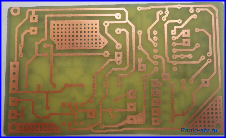
The tracks on this board are made with a width of 0.8 mm, almost all pads are 1.5 mm in diameter, and almost all holes are made with a 0.7 mm drill. I think that it will not be very difficult for you to understand this board, and also, depending on the parts used (especially the trimmers), make your own changes. I want to say right away that this board has been tested and if the parts are soldered correctly, the circuit starts working immediately.
A little about the functionality and beauty of the board. When you pick up a factory-made board, you probably noticed how conveniently it is prepared for soldering parts - so-called “silk-screen printing” is applied on top and bottom in white, on which the names of the parts and their locations are immediately visible, which makes life very easy when soldering radioelements. Seeing seat radio element, you will never be mistaken in which holes to insert it into, all you have to do is look at the diagram, select the desired part, insert it and solder it. Therefore, today we will make a board close to the factory one, i.e. Let's apply silk-screen printing to the layer from the parts side. The only thing is that this “silk-screen printing” will be black. The process is very simple. If, for example, we use Sprint program Layout, then when printing we select layer K1 (the layer on the parts side), print it as for the board itself (but only in mirror image), put a print on the side of the board where there is no foil (on the parts side), center it (and on the clearance of the etched board, the pattern is clearly visible) and using the LUT method we transfer the toner to the textolite. The process is the same as when transferring toner to copper, and we admire the result:
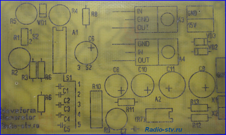
After drilling the holes, you will actually see the layout of the parts on the board. And the most important thing is that this is not only for the beauty of the board (although, as I already said, a beautiful board is the key to good and long-term operation of the circuit you have assembled), but most importantly, to facilitate further soldering of the circuit. The ten minutes spent on applying “silk-screen printing” significantly pays off in time when assembling the circuit. Some radio amateurs, after preparing the board for soldering and applying such “silk-screen printing,” cover the layer on the parts side with varnish, thereby protecting the “silk-screen printing” from being erased. I would like to note that the toner on the PCB adheres very well, and after soldering the parts you will have to remove the remaining rosin from the board with a solvent. Contact of solvent on “silk-screen printing” coated with varnish leads to the appearance of white plaque, when removed, the “silk-screen printing” itself comes off (this is clearly visible in the photograph, this is exactly what I did), therefore, I believe that it is not necessary to use varnish. By the way, all the inscriptions and contours of parts are made with a line thickness of 0.2 mm, and as you can see, all this is perfectly transferred to the textolite.
And this is what my board looks like (without jumpers and attachments):
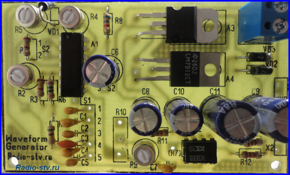
This board would have looked much better if I hadn't varnished it. But you can, as always, experiment and, of course, do better. In addition, I have two C4 capacitors installed on the board; I didn’t have the required value (0.22 μF), so I replaced it with two 0.1 μF capacitors connecting them in parallel.
Let's continue. After we have soldered all the parts onto the board, we solder two jumpers and solder resistors R7 and R10 and switch S2 using sections of mounting wires. We do not solder switch S1 yet, but make a jumper from a wire, connecting pins 10 of the ICL8038 microcircuit and capacitor C3 (i.e., we connect the range 0.7 - 7 kHz), supply power from our (I hope assembled) laboratory power supply to the inputs of microcircuit stabilizers about 15 volts DC voltage
Now we are ready to test and configure our generator. How to check the functionality of the generator. Very simple. We solder to outputs X1 (1:1) and “common” any ordinary or piezoceramic speaker (for example, from a Chinese clock in an alarm clock). When the power is connected, we will hear a beep. When changing resistance R10, we will hear how the tone of the output signal changes, and when changing resistance R7, we will hear how the volume of the signal changes. If you don’t have this, then the only reason is improper soldering of the radio elements. Be sure to go through the scheme again, eliminate the shortcomings and everything will be ok!
We will assume that we have passed this stage of generator manufacturing. If something doesn’t work out, or it works out but not right, be sure to ask your questions in the comments or on the forum. Together we will solve any problem.
Let's continue. This is what the board looks like ready for setup:
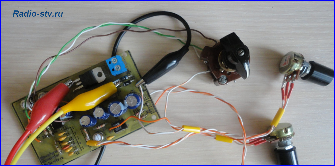
What we see in this picture. Power supply – black “crocodile” to the common wire, red “crocodile” to the positive input of the stabilizer, yellow “crocodile” - to the negative input of the negative voltage stabilizer. Soldered variable resistances R7 and R10, as well as switch S2. From our laboratory power supply (this is where the bipolar power supply comes in handy), we supply a voltage of about 15-16 volts to the circuit, so that the 12-volt microcircuit stabilizers work normally.
Having connected power to the inputs of the stabilizers (15-16 volts), use a tester to check the voltage at the outputs of the stabilizers (±12 volts). Depending on the voltage stabilizers used, the voltage will differ from ± 12 volts, but is close to it. If your voltages at the outputs of the stabilizers are absurd (do not correspond to what is needed), then there is only one reason - poor contact with ground. The most interesting thing is that even the absence of reliable contact with the “ground” does not interfere with the operation of the generator on the speaker.
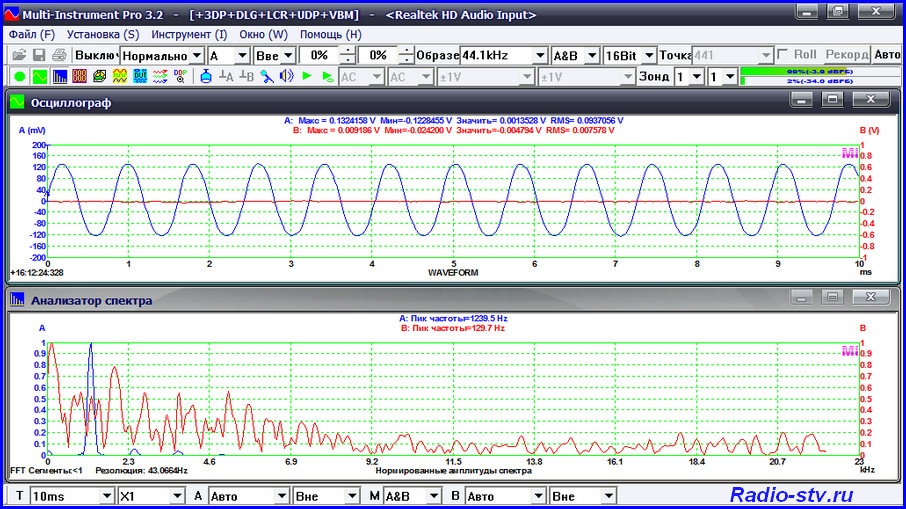
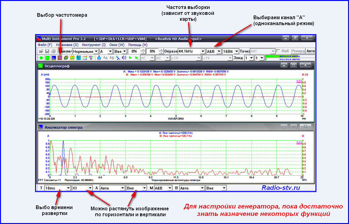
Well, now we just need to configure our generator. We will carry out the setup using a special program - virtual oscilloscope. On the Internet you can find many programs that simulate the operation of an oscilloscope on a computer screen. Especially for this lesson, I checked many such programs and chose one, which, it seems to me, simulates an oscilloscope the best - Virtins Multi-Instrument. This program includes several subprograms - an oscilloscope, a frequency meter, a spectrum analyzer, a generator, and in addition there is a Russian interface:
Here you can download this program:
(41.7 MiB, 4,326 hits)
The program is easy to use, and to configure our generator you only need minimal knowledge of its functions:
In order to configure our generator, we need to connect to the computer via a sound card. You can connect through the line input (not all computers have it) or to the microphone connector (available on all computers). To do this, we need to take some old, unnecessary headphones from a phone or other device, with a plug with a diameter of 3.5 mm, and disassemble them. After disassembly, solder two wires to the plug - as shown in the photo:
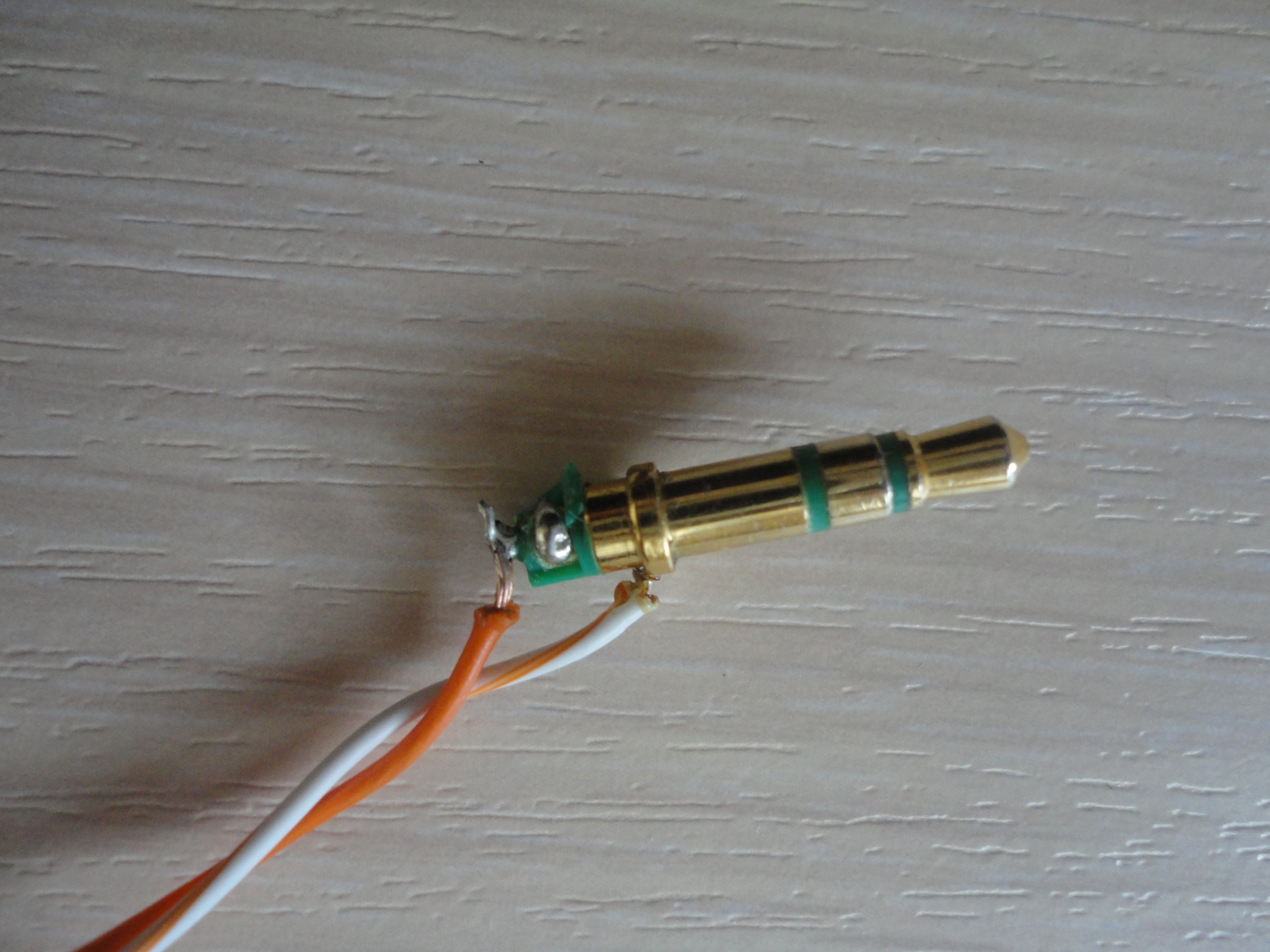
After this, solder the white wire to ground and the red wire to pin X2 (1:10). We set the R7 signal level control to the minimum position (be sure to not burn the sound card) and connect the plug to the computer. We launch the program, and in the working window we will see two running programs - an oscilloscope and a spectrum analyzer. Turn off the spectrum analyzer, select “multimeter” on the top panel and launch it. A window will appear that will show the frequency of our signal. Using resistor R10 we set the frequency to about 1 kHz, set switch S2 to position “1” (sinusoidal signal). And then, using trimming resistors R2, R4 and R5, we configure our generator. First, the shape of a sinusoidal signal with resistors R5 and R4, achieving a sine wave shape on the screen, and then, switching S2 to position “3” (rectangular signal), using resistor R2 we achieve signal symmetry. You can see what it really looks like in this short video:
After completing the steps and setting up the generator, we solder switch S1 to it (after removing the jumper) and assemble the entire structure in a ready-made or homemade (see lesson on assembling a power supply) case.
Let's assume that we have successfully dealt with everything, and a new device has appeared in our amateur radio equipment - function generator . We will not equip it with a frequency meter yet (there is no suitable circuit) but will use it in this form, given that we can set the frequency we need using the program Virtins Multi-Instrument. We will assemble a frequency meter for the generator on a microcontroller, in the “Microcontrollers” section.
Our next stage in the knowledge and practical implementation of amateur radio devices will be the assembly of a light-and-music installation using LEDs.
When repeating this design, there was a case when it was not possible to achieve correct form rectangular pulses. It is difficult to say why such a problem arose, perhaps because of the way the chip works. Solving the problem is very easy. To do this, you need to use a Schmitt trigger on the K561(KR1561)TL1 chip according to the diagram below. This circuit allows you to convert voltage of any shape into rectangular pulses with a very good shape. The circuit is connected to the gap in the conductor coming from pin 9 of the microcircuit, instead of capacitor C6. 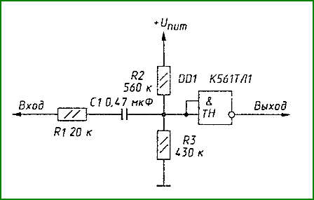
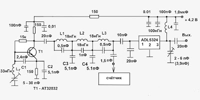
A simple generator of low and high frequency signals is intended for setting up and testing various instruments and devices manufactured by radio amateurs.
The low frequency generator produces a sinusoidal signal in the range from 26 Hz to 400 kHz, which is divided into five subranges (26...240, 200...1500 Hz: 1.3...10, 9...60, 56... 400 kHz). The maximum amplitude of the output signal is 2 V. The harmonic coefficient over the entire frequency range does not exceed 1.5%. Uneven frequency response - no more than 3 dB. Using the built-in attenuator, you can attenuate the output signal by 20 and 40 dB. There is also a smooth adjustment of the amplitude of the output signal with its control using a measuring device.
The high frequency generator produces a sinusoidal signal in the range from 140 kHz to 12 MHz (subranges 140...340, 330...1000 kHz, 1...2.8,2.7...12 MHz).
The high-frequency signal can be modulated in amplitude by a signal from both the internal low-frequency generator. and from the outside.
The maximum amplitude of the output voltage is 0.2 V. The generator provides smooth adjustment of the output voltage with amplitude control using a measuring device.
The supply voltage for both generators is 12 V.
The schematic diagram of the device is shown in Fig. 1.
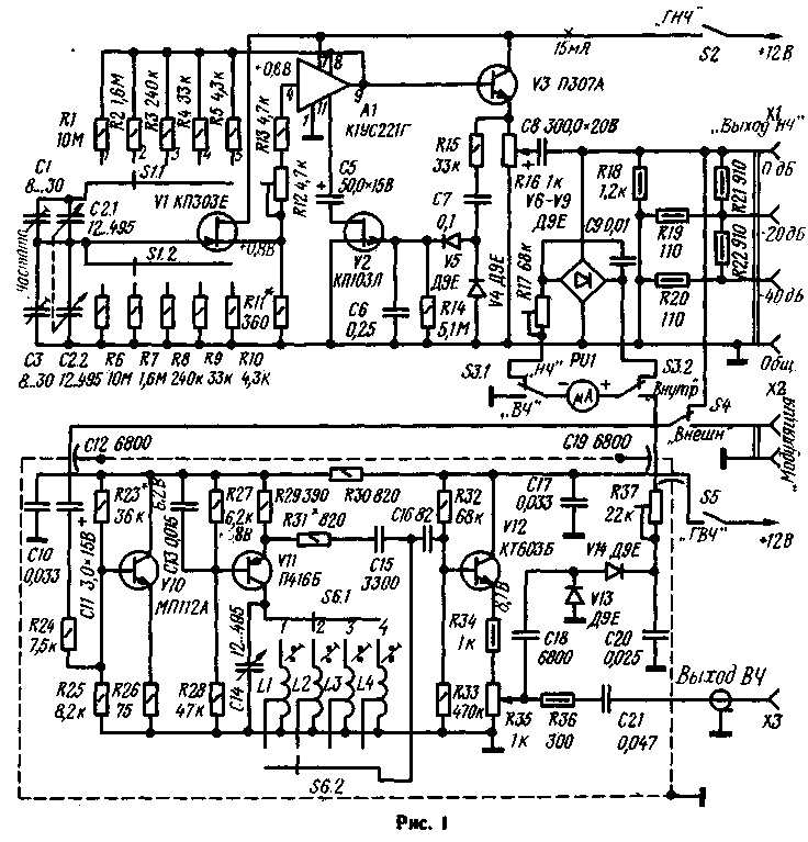
The low frequency generator is based on a well-known circuit. The frequency of the generated signal is changed by a dual variable capacitor C2. The use of a block of variable capacitors to generate low (30...100 Hz) frequencies required a high input impedance of the generator amplifier. Therefore, the signal from the bridge goes to the flow follower on the field-effect transistor V1, and then to the input of a two-stage amplifier with direct connections (chip A1). From the output of the microcircuit, the signal is supplied to the output emitter follower on transistor V3 and to the second diagonal of the bridge. From resistor R16, the signal is supplied to the output voltage divider (resistors R18-R22) and to the measuring device PU1. which controls the amplitude of the output signal.
On field-effect transistor V2, a cascade for stabilizing the amplitude of the output voltage is assembled, which operates as follows. The output signal from the emitter of transistor V3 is rectified by diodes (V4, V5), and a constant voltage proportional to the amplitude of the output signal is applied to the gate of transistor V2, which plays the role of a variable resistance. If, for example, for some reason (the temperature has changed environment or supply voltage, etc.) the amplitude of the output signal has increased, then the positive voltage supplied to the gate of transistor V2 will also increase. The dynamic resistance of the transistor channel will also increase, which will lead to an increase in the negative feedback coefficient in microcircuit A1, the gain of the latter will decrease, which will lead to the restoration of the amplitude of the output signal.
The connection between the source follower on transistor V1 and the input of microcircuit A1 is galvanic. This made it possible to eliminate the large-capacity transition capacitor and improve the phase response of the generator. The optimal transmission coefficient is set by trimming resistor R12.
The high frequency generator is made of three transistors V10-V12. The master oscillator is assembled on transistor V11, connected according to the circuit with common base. The cascade does not have any special features. The required range is selected by switching the contour coils. Within the sub-band, the frequency is smoothly changed by a variable capacitor C14. The output stage is an emitter follower on transistor V12. The signal is supplied to it from part of the turns of the loop coil, which further reduces the influence of the load on the frequency stability of the generator.
From resistor R35, the high-frequency voltage is supplied to the rectifier (diodes V13, V14), and the rectified voltage through resistor R37 is supplied to the PUI measuring device, which controls the output signal voltage.
A modulating stage is assembled on transistor V10, connected according to a common emitter circuit. Its load is the master generator. Thus, the master oscillator operates with an alternating supply voltage, therefore the amplitude of the generator output voltage also changes, resulting in amplitude modulation. This design of the generator made it possible to obtain a modulation depth from 0 to 70%. A low-frequency signal can be supplied to the modulator from either an internal or external generator.
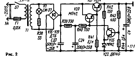
Both generators are powered by a rectifier with a stabilizer (Fig. 2), made according to a standard circuit.
Both generators and the mains power supply are made in the form of separate units installed in a common housing. The PU1 measuring device is also common to generators. The high-frequency generator block is covered with a brass screen.
The RF generator coils are wound on frames from the IF circuits of the Start-3 TV with carbonyl trimmers. In Fig. Figure 3 shows sketches of the coil frames. Their winding data is given in the table. Coils L1. L2, L3 are wound in bulk, and coil L4 is wound turn to turn. The T1 transformer was used ready-made from the Efir-M radio. When making a transformer yourself, it should be wound on a Ш16Х24 core. The network winding for a voltage of 220 V should contain 2580 turns of wire G1EV-2 0.15, the secondary winding - 208 turns of wire PEV-1 0.59.
![]()
Puc.3
The scales of the device are glued onto disks with a diameter of 90 mm, which, together with the pulleys of the vernier device, are fixed on the axes of variable capacitors.
Instead of the KP103L transistor, you can use the KP102E. This replacement may even slightly improve the parameters of the generator.
Setting up a low-frequency generator begins with selecting resistor R11. To do this, open the circuit R12, R13. A high-resistance voltmeter measures the voltage at the input of microcircuit A1 (pin 4). Then, selecting resistor R11 in the range from 300 Ohms to 1.5 kOhms, we achieve the same voltage at the source of transistor V1. If this cannot be done, you should select transistor V1. (It may turn out that it will not be possible to select such a transistor, then you should decouple the input of the microcircuit from the source of transistor V1 by direct current, connecting a capacitor with a capacity of 50 μF into the open circuit.) Having restored the open circuit, change the resistance of resistor R12 so as to obtain at the output of the generator signal without distortion, monitoring its shape using an oscilloscope. With a further decrease in the resistance of this resistor, a symmetrical limitation of the signal should occur. Having set the amplitude of the output signal to about 2 V and selected the required resistance of resistor R17 in the PU1 circuit, the installation of the low-frequency generator is considered complete.
Setting up an RF generator begins with a modulating stage. By selecting resistor R23, a voltage of 6.2 V is set on the collector of transistor V10. Setting up the master oscillator consists of selecting resistor R31 in the positive feedback circuit. In this case, the shape of the output signal is monitored using an oscilloscope. They do this in the low-frequency subrange. If the oscilloscope parameters allow, the test is also done on other frequency subranges. Then select resistor R37 in the circuit of the measuring device.
Having completed the adjustment of the blocks and checked their operation in all sub-bands, they begin to select the elements of the frequency-setting circuits and achieve the required overlap, after which the device is calibrated according to one of the methods repeatedly described in the radio engineering literature and the Radio magazine.
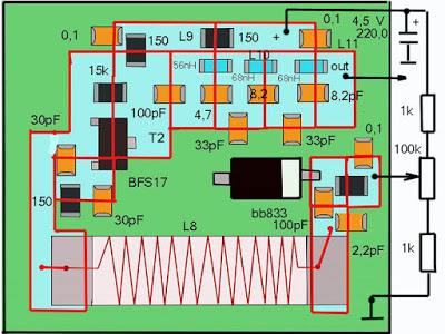
The idea to make an inexpensive VHF generator for use in the field was born when the desire arose to measure the parameters of self-assembled antennas homemade SWR meter. It was possible to make such a generator quickly and conveniently using replaceable module blocks. I have already assembled several generators for: broadcasting 87.5 - 108 MHz, amateur radio 144 - 146 MHz and 430 - 440 MHz, including PRM (446 MHz) bands, terrestrial digital television range 480 - 590 MHz. Such a mobile and simple measuring device fits in your pocket, and in some respects it is not inferior to professional measuring instruments. The scale bar can be easily supplemented by changing several values in the circuit or the modular board.
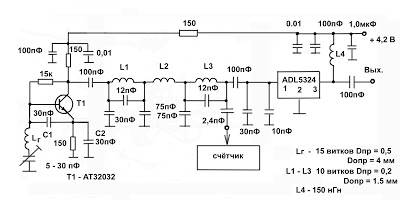
Block diagram is the same for all used ranges.
This master oscillator(on transistor T1) with parametric frequency stabilization, which determines the required overlap range. To simplify the design, range tuning is carried out by a trimming capacitor. In practice, such a switching circuit, with appropriate ratings, on standardized chip inductors and chip capacitors, was tested up to frequency 1300 MHz.
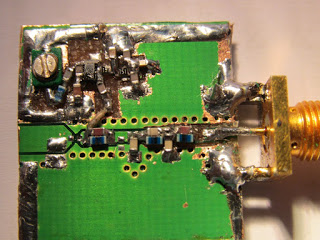 |
| Photo 2. Generator with low-pass filter for the ranges 415 - 500 MHz and 480 - 590 MHz. |
Low pass filter (LPF) suppresses higher harmonics by more than 55 dB, made on circuits with inductors L 1, L 2, L 3. Capacitors parallel to the inductances form notch filters tuned to the second harmonic of the local oscillator, which provides additional suppression of higher harmonics of the local oscillator.
Linear amplifier on the microcircuit has a normalized output impedance of 50 Ohms and for this switching circuit it develops a power of 15 to 25 mW, sufficient for tuning and checking antenna parameters, which does not require registration. This is exactly the output power of the high-frequency generator G4-176. For the simplicity of the circuit, there is no low-pass filter at the output of the microcircuit, so the suppression of higher harmonics of the generator at the output has deteriorated by 10 dB.
The ADL 5324 chip is designed to operate at frequencies from 400 MHz to 4 GHz, but practice has shown that it is quite efficient at more low frequencies VHF band.
Power supply for generators carried out from a lithium battery with a voltage of up to 4.2 volts. The device has a connector for external power supply and battery recharging and a high-frequency connector for connecting an external meter, and a homemade SWR meter can serve as a level indicator.
Generator range 87.5 – 108 MHz.
Options. The actual frequency tuning was 75 – 120 MHz. Supply voltage V p = 3.3 – 4.2 V. Output power up to 25 mW (V p = 4 V). Output resistance Rout = 50 Ohm. Suppression of higher harmonics more than 40 dB. Unevenness in the frequency range 87.5 – 108 MHz is less than 2 dB. Current consumption is no more than 100 mA (V p = 4 V).
 |
| Rice. 1. Generator range 87.5 - 108 MHz. |
 |
| Rice. 2. |
Generator of the amateur radio range 144 - 146 MHz.
Options. The actual frequency tuning was 120 – 170 MHz. Supply voltage V p = 3.3 – 4.2 V. Output power up to 20 mW (V p = 4 V). Output resistance Rout = 50 Ohm. Suppression of higher harmonics more than 45 dB. Unevenness in the frequency range is less than 1 dB. Current consumption is no more than 100 mA (V p = 4 V).
In the generator, the inductor coil is reduced to 10 turns (mandrel diameter 4 mm, wire diameter 0.5 mm). The values of the low-pass filter capacitors have decreased.
Generator of the amateur radio range 430 - 440 MHz.
Options. The actual tuning range at the indicated ratings was 415 – 500 MHz. Supply voltage V p = 3.3 – 4.2 V. Output power up to 15 mW (V p = 4 V). Output resistance Rout = 50 Ohm. Suppression of higher harmonics more than 45 dB. Unevenness in the frequency range 430 – 440 MHz is less than 1 dB. Current consumption is no more than 95 mA (V p = 4 V).
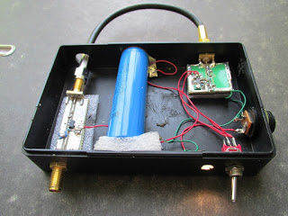 |
| Photo 6. Design of the generator for the range 415 - 500 MHz and 480 - 590 MHz. |
Generator of the terrestrial digital television range 480 – 590 MHz.
Options. The actual tuning range at the indicated ratings was 480 – 590 MHz. Supply voltage V p = 3.3 – 4.2 V. Output power up to 15 mW (V p = 4 V). Output resistance Rout = 50 Ohm. Suppression of higher harmonics more than 45 dB. Unevenness in the frequency range is less than 1 dB. Current consumption is no more than 95 mA (V p = 4 V).
 |
| Fig. 3 Generator range 480 - 490 MHz. Generator range 415 -500 MHz. Lg = 47 nH. C3, C4 -5.6 pF. |
-
 April 17, 2015Features of the breakdown of alcohol in the body
 -
 April 17, 2015Some tips to relieve allergy symptoms


